I am hoping that you have already gone through my previous post Python binding with IDE.
In that post, I would have demonstrated it for Visual Studio IDE, but using Boost's own build tool bjam.
In this post, I am gonna explain how to configure Visual Studio to build out Python binding C++ code without bjam and the additional files it depends on(boost_build.jam and Jamroot. Its a relief that you dont have to change the Jamroot file accordingly, if your projects are in different folders. Helped me to resolve a lot of dependency issues without using bjam). But I would recommend bjam, if all your project files are in the same source directory. Its a great build tool by Boost!
Okay, lets get started.
- Start with an Empty C++ Project as mentioned earlier
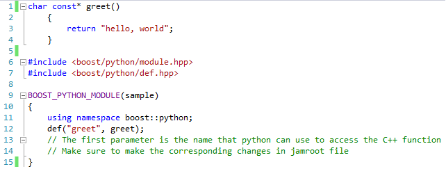
(File->New->Project Select Under 'Visual C++', select 'Empty Project') - Create a new C++ file, say hello.cpp Copy the contents of the already existing hello.cpp from .../examples/tutorial.
- Open Project properties page. Right-click Project, select Properties. Make the following changes in that window
- Under 'General' :
Target Extension : .pyd
Configuration Type : Change to Static Library(.lib) ( Really have no idea why we have to do this, but the other Configuration types may cause unnecessary link errors , Dll worked for me though :) )
- Under 'VC++ Directories' :
Include Directories, add C:\Boost\1.55.0;C:\Python27\include;
Library Directories, add C:\Boost\1.55.0\stage\lib;C:\Python27\libs;
( Note : Add appropriate file location in your system )
- Under 'Linker' , you will have to add boost-python library and python library as shown below. (Copy the lib name, available under ..\Python27\libs\ and ..\Boost\1.55.0\stage\lib\ and press OK.
- Go ahead and build the file. You will find a *.pyd file either in your Project source directory or under Debug folder.
- Dont forget the most important step : Make sure to copy the boost_python-vc110-mt-gd-1_55.dll file available under ..\Boost\1.55.0\stage\lib\. Copy it to wherever your *.pyd file is.
Then run your code using Python interpreter as mentioned in the previous post(Boost.Python setup )
Hope you got the desired output.
Feel free to provide your comments below!!!